Productlist
Contact us
Add:NO.29.Huancheng East RD.,Liushi,Yueqing,Zhejiang,China 325604
TEL:0086-577-62762532
Fax:0086-577-62762535
E-mail:laurence@powerfitting.cn
laurence9977@vip.sohu.com
powerfittings@gmail.com
Linkman:Laurence
http://www.abcfitting.cn
TEL:0086-577-62762532
Fax:0086-577-62762535
E-mail:laurence@powerfitting.cn
laurence9977@vip.sohu.com
powerfittings@gmail.com
Linkman:Laurence
http://www.abcfitting.cn
Product show
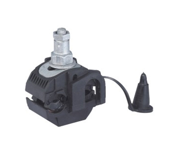
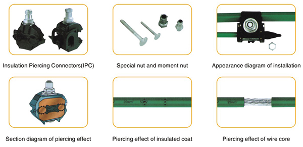
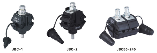
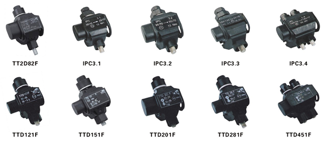
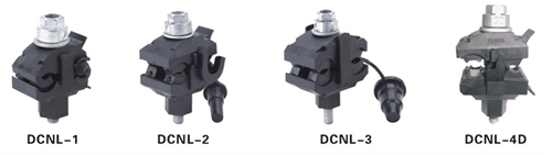
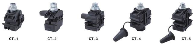
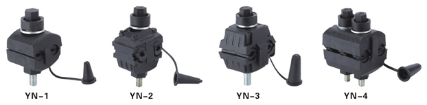
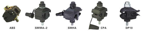
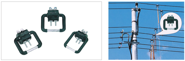
Insulation piercing connector
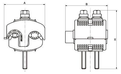
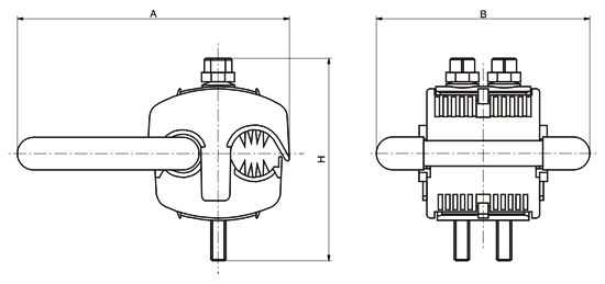
| General of insulation piercing connector(IPC) | ||||||||||||||||||||||||||||||||||||||||||||||||||||||||||||||||||||||||||||||||||||||||||||||||||
| 1.1 Piercing connector,simple installation.need not strip the cable coat. 1.2 Moment nut,piercing pressure is constant,keep good electric connection and make no damage to lead. 1.3 Self-seam frame,wetproof,and anti-corrosion,extend the using life of insulated lead and connector 1.4 A dopted special connecting tablet,apply to joint of Cu(AL)and Cu(AL)or Cu and Al 1.5 Small electric connecting resistance,connecting resistance less than 1.1 times of the resistance of branch conductor with teh same length. 1.6 Special insulated case body,resistandce to illumination and environmental aging.the insulation strength can up to 12kV 1.7 Arc surface design,apply to connectrion with the same(different)diameter,wide connectrion scope(0.75mm2-400mm2) | ||||||||||||||||||||||||||||||||||||||||||||||||||||||||||||||||||||||||||||||||||||||||||||||||||
| (Performacnce testing) | ||||||||||||||||||||||||||||||||||||||||||||||||||||||||||||||||||||||||||||||||||||||||||||||||||
| 2.1 Mechanical performance:the grip force of the wire clamp is 1/10 bigger the the break force of the lead.It comply with GB/T2317.3-2000,the heat circle trial standard for elcetic fitting. 2.2 Temperature rise performance:under the condition of big current.the temperature rise of connector is less than that of connection lead. 2.3 Heat circle performance:conforms to GB/T2317.3-2000,the heat circle trial standard for elcetirc fitting. 2.4 Waterproof insulation performance:conforms to the relecant requirements in Part 2 of GB/T13140.4-1998 2.5 Resistance to corrosion performance:under the condition of SO2 and salt fog.it can do three times of foureteen days circle testing. 2.6 Environmental aging performance:under the circumstance of ultraviolet.radiation,dry and moist,expose if with change of temperature and heat impulse for six weeks. 2.7 Fire-proof performance:insulation material of the connectror with stands glowing filament test,Conform to the requirements in Chapter4-10 of GB/T5169.4. | ||||||||||||||||||||||||||||||||||||||||||||||||||||||||||||||||||||||||||||||||||||||||||||||||||
 | ||||||||||||||||||||||||||||||||||||||||||||||||||||||||||||||||||||||||||||||||||||||||||||||||||
| (Simple installation) | ||||||||||||||||||||||||||||||||||||||||||||||||||||||||||||||||||||||||||||||||||||||||||||||||||
 | ||||||||||||||||||||||||||||||||||||||||||||||||||||||||||||||||||||||||||||||||||||||||||||||||||
| The reason of choosing insulation piecring connector(IPC) | ||||||||||||||||||||||||||||||||||||||||||||||||||||||||||||||||||||||||||||||||||||||||||||||||||
| 3.1 Simple installation Con be branch of cable without striping the insulated coat and the joint is completely insulated.Make branch in the random location of cable without cutting off the main cable.Smiple and reliable installation,just need sleever spanner,can be installed with on live line. 3.2 Safe use The joint has good resistance to distorion,quake,fire,wet,electrochemical corrosion and aging,need no maintenance,Has been used successfully for 30 years, 3.3 Economical cost Small installation space.save the cost of bridge and land construction.In structural application.there need no terminal box.junction box and return wire of cable,save cost.The cost of cables and clamps is lower than other power supply system. | ||||||||||||||||||||||||||||||||||||||||||||||||||||||||||||||||||||||||||||||||||||||||||||||||||
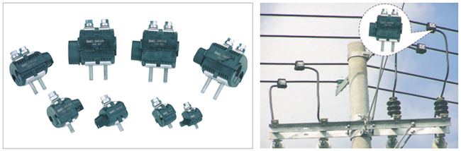
| SME series | ||||||||||||||||||||||||||||||||||||||||||||||||||||||||||||||||||||||||||||||||||||||||||||||||||
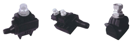 | ||||||||||||||||||||||||||||||||||||||||||||||||||||||||||||||||||||||||||||||||||||||||||||||||||
| Insulation piercing connectors | ||||||||||||||||||||||||||||||||||||||||||||||||||||||||||||||||||||||||||||||||||||||||||||||||||
 | ||||||||||||||||||||||||||||||||||||||||||||||||||||||||||||||||||||||||||||||||||||||||||||||||||
| Product type and application scope | ||||||||||||||||||||||||||||||||||||||||||||||||||||||||||||||||||||||||||||||||||||||||||||||||||
| 1KV Series products (Low voltage series) | ||||||||||||||||||||||||||||||||||||||||||||||||||||||||||||||||||||||||||||||||||||||||||||||||||
| ||||||||||||||||||||||||||||||||||||||||||||||||||||||||||||||||||||||||||||||||||||||||||||||||||
 | ||||||||||||||||||||||||||||||||||||||||||||||||||||||||||||||||||||||||||||||||||||||||||||||||||
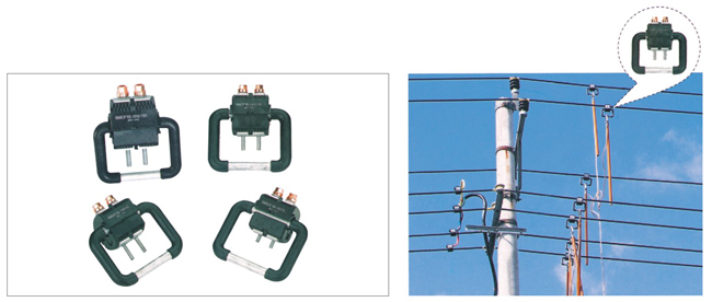
| Insulation piercing connectors | ||||||||||||||||||||||||||||||||||||||||||||||||||||||||||||||||||||||||||||||||||||||||||||||||||
 | ||||||||||||||||||||||||||||||||||||||||||||||||||||||||||||||||||||||||||||||||||||||||||||||||||
 | ||||||||||||||||||||||||||||||||||||||||||||||||||||||||||||||||||||||||||||||||||||||||||||||||||
 | ||||||||||||||||||||||||||||||||||||||||||||||||||||||||||||||||||||||||||||||||||||||||||||||||||
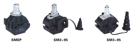
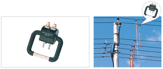
| SMC Piercing connector(1kV) | ||||||||||||||||||||||||||||||||||||||||||||||||||||||||||||||||||||||||||||||||||||||||||||||||||
| Application | ||||||||||||||||||||||||||||||||||||||||||||||||||||||||||||||||||||||||||||||||||||||||||||||||||
| Applicable to branch connection and succession for 1kv insulated overhead distribution systems. | ||||||||||||||||||||||||||||||||||||||||||||||||||||||||||||||||||||||||||||||||||||||||||||||||||
 | ||||||||||||||||||||||||||||||||||||||||||||||||||||||||||||||||||||||||||||||||||||||||||||||||||
 | ||||||||||||||||||||||||||||||||||||||||||||||||||||||||||||||||||||||||||||||||||||||||||||||||||
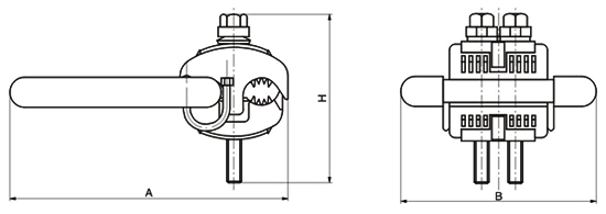
| Technical Data | ||||||||||||||||||||||||||||||||||||||||||||||||||||||||||||||||||||||||||||||||||||||||||||||||||
| ||||||||||||||||||||||||||||||||||||||||||||||||||||||||||||||||||||||||||||||||||||||||||||||||||
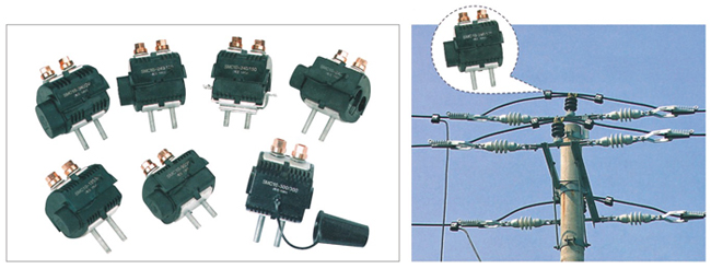
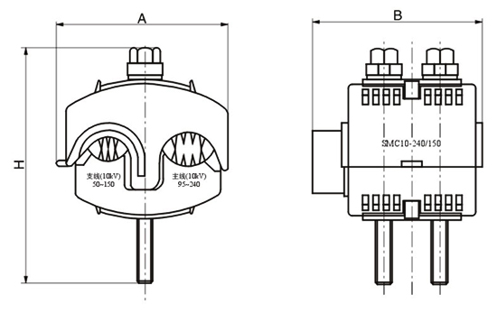
| SMC Piercing connector(10kV) | ||||||||||||||||||||||||||||||||||||||||||||||||||||||||||||||||||||||||||||||||||||||||||||||||||
| Application | ||||||||||||||||||||||||||||||||||||||||||||||||||||||||||||||||||||||||||||||||||||||||||||||||||
| Applicable to branch connection and succession for 10kv insulated overhead distribution systems. | ||||||||||||||||||||||||||||||||||||||||||||||||||||||||||||||||||||||||||||||||||||||||||||||||||
 | ||||||||||||||||||||||||||||||||||||||||||||||||||||||||||||||||||||||||||||||||||||||||||||||||||
 | ||||||||||||||||||||||||||||||||||||||||||||||||||||||||||||||||||||||||||||||||||||||||||||||||||
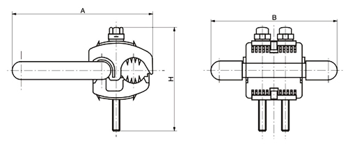
| Technical Data | ||||||||||||||||||||||||||||||||||||||||||||||||||||||||||||||||||||||||||||||||||||||||||||||||||
| ||||||||||||||||||||||||||||||||||||||||||||||||||||||||||||||||||||||||||||||||||||||||||||||||||
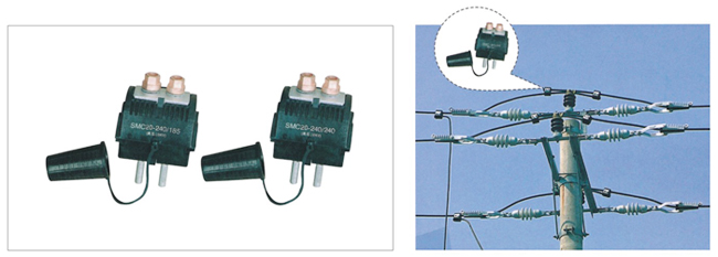
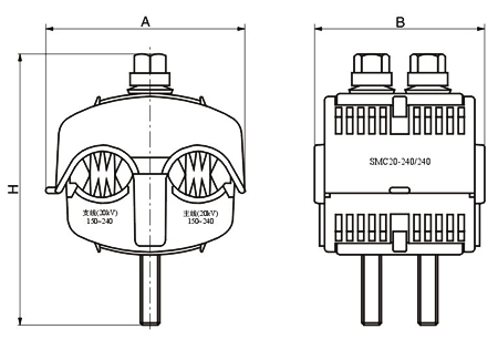
| SMC Piercing connector(20kV) | ||||||||||||||||||||||||||||||||||||||||||||||||||||||||||||||||||||||||||||||||||||||||||||||||||
| Application | ||||||||||||||||||||||||||||||||||||||||||||||||||||||||||||||||||||||||||||||||||||||||||||||||||
| Applicable to branch connection and succession for 20kv insulated overhead distribution systems. | ||||||||||||||||||||||||||||||||||||||||||||||||||||||||||||||||||||||||||||||||||||||||||||||||||
 | ||||||||||||||||||||||||||||||||||||||||||||||||||||||||||||||||||||||||||||||||||||||||||||||||||
 | ||||||||||||||||||||||||||||||||||||||||||||||||||||||||||||||||||||||||||||||||||||||||||||||||||
| Technical Data | ||||||||||||||||||||||||||||||||||||||||||||||||||||||||||||||||||||||||||||||||||||||||||||||||||
| ||||||||||||||||||||||||||||||||||||||||||||||||||||||||||||||||||||||||||||||||||||||||||||||||||
| SMCF Piercing grounding protection(1kV) | ||||||||||||||||||||||||||||||||||||||||||||||||||||||||||||||||||||||||||||||||||||||||||||||||||
| Application | ||||||||||||||||||||||||||||||||||||||||||||||||||||||||||||||||||||||||||||||||||||||||||||||||||
| Applicable to grounding protection during electric power construction for 1kV or below insulated overhead line. | ||||||||||||||||||||||||||||||||||||||||||||||||||||||||||||||||||||||||||||||||||||||||||||||||||
 | ||||||||||||||||||||||||||||||||||||||||||||||||||||||||||||||||||||||||||||||||||||||||||||||||||
 | ||||||||||||||||||||||||||||||||||||||||||||||||||||||||||||||||||||||||||||||||||||||||||||||||||
| Technical Data | ||||||||||||||||||||||||||||||||||||||||||||||||||||||||||||||||||||||||||||||||||||||||||||||||||
| ||||||||||||||||||||||||||||||||||||||||||||||||||||||||||||||||||||||||||||||||||||||||||||||||||
| SMCF Piercing grounding protection(10kV) | ||||||||||||||||||||||||||||||||||||||||||||||||||||||||||||||||||||||||||||||||||||||||||||||||||
| Application | ||||||||||||||||||||||||||||||||||||||||||||||||||||||||||||||||||||||||||||||||||||||||||||||||||
| Applicable to grounding protection during electric power construction for 10kV or below insulated overhead line. | ||||||||||||||||||||||||||||||||||||||||||||||||||||||||||||||||||||||||||||||||||||||||||||||||||
 | ||||||||||||||||||||||||||||||||||||||||||||||||||||||||||||||||||||||||||||||||||||||||||||||||||
 | ||||||||||||||||||||||||||||||||||||||||||||||||||||||||||||||||||||||||||||||||||||||||||||||||||
| Technical Data | ||||||||||||||||||||||||||||||||||||||||||||||||||||||||||||||||||||||||||||||||||||||||||||||||||
| ||||||||||||||||||||||||||||||||||||||||||||||||||||||||||||||||||||||||||||||||||||||||||||||||||
| SMCF Piercing grounding protection(20kV) | ||||||||||||||||||||||||||||||||||||||||||||||||||||||||||||||||||||||||||||||||||||||||||||||||||
| Application | ||||||||||||||||||||||||||||||||||||||||||||||||||||||||||||||||||||||||||||||||||||||||||||||||||
| Applicable to grounding protection during electric power construction for 20kV or below insulated overhead line. | ||||||||||||||||||||||||||||||||||||||||||||||||||||||||||||||||||||||||||||||||||||||||||||||||||
 | ||||||||||||||||||||||||||||||||||||||||||||||||||||||||||||||||||||||||||||||||||||||||||||||||||
 | ||||||||||||||||||||||||||||||||||||||||||||||||||||||||||||||||||||||||||||||||||||||||||||||||||
| Technical Data | ||||||||||||||||||||||||||||||||||||||||||||||||||||||||||||||||||||||||||||||||||||||||||||||||||
| ||||||||||||||||||||||||||||||||||||||||||||||||||||||||||||||||||||||||||||||||||||||||||||||||||
